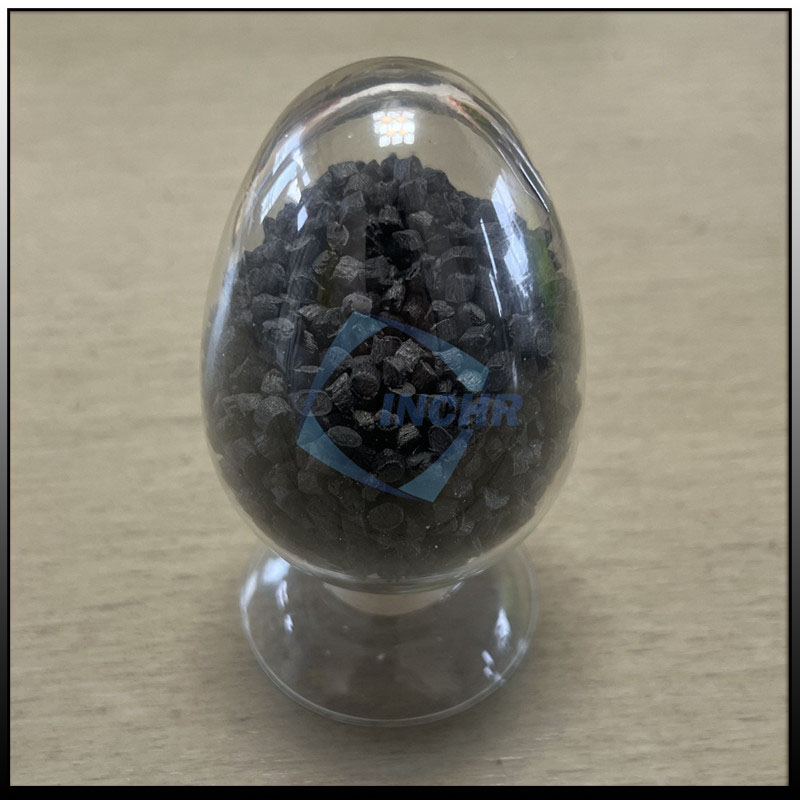
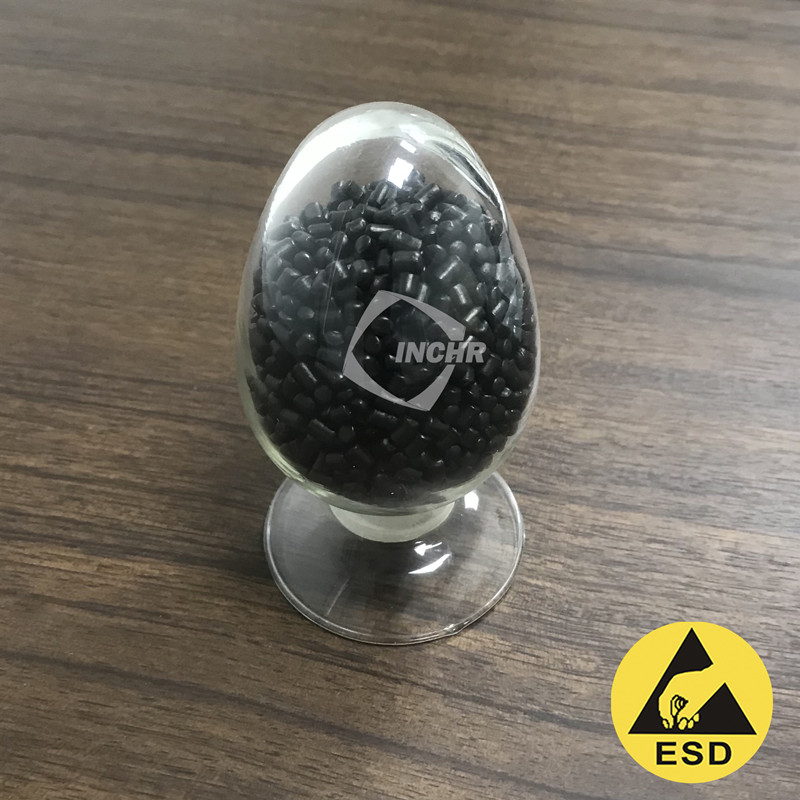
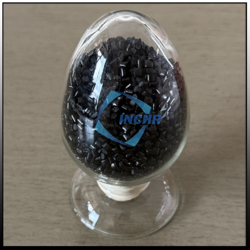
Carbon fiber reinforced nylon (PA) is the thermoplastic most often chosen to replace metal parts. It brings tensile strength into the range of cast aluminum, cuts weight by roughly half, and keeps wear resistance and fatigue behavior that unfilled nylon cannot match. For gears, brackets, housings, and structural components once machined from metal, carbon fiber reinforced nylon (PA) offers a path to lighter parts, lower system cost, and design freedom — if the conversion is done properly. This guide explains where carbon fiber reinforced PA wins, what changes during metal-to-plastic conversion, and how to validate the result before it goes into production.
Why Engineers Replace Metal with Carbon Fiber Nylon PA
The material is a nylon matrix — usually PA6 or PA66 — reinforced with short carbon fiber. The fiber carries load, the nylon resists impact and wear, and the combination outperforms either material alone. The practical reasons to switch are consistent across industries:
- Weight reduction — carbon fiber nylon PA parts typically weigh 40–50% less than equivalent aluminum parts, and far less than steel.
- Strength-to-weight ratio — high tensile and flexural strength with density of roughly 1.2–1.4 g/cm³, versus 2.7 for aluminum and 7.8 for steel.
- Wear and self-lubrication — with the right fiber and additive package, CF-PA gears and bearings outlast metal in many dry-running applications.
- Fatigue and creep resistance — carbon fiber raises the endurance limit and keeps parts dimensionally stable under sustained load.
- Integration and part count — bosses, clips, and snap fits let one molded part replace a welded or bolted metal assembly.
- Damping and noise — composites damp vibration better than metal, reducing noise in transmissions and casings.
The trade-offs also deserve equal attention: carbon fiber nylon PA is more expensive per kilogram than metal on a weight basis, absorbs moisture that shifts dimensions, and needs drying and careful gate design in molding. The conversion pays off when the part is designed around the material, not simply copied from the metal drawing.
Parts That Migrate from Metal to Carbon Fiber Nylon PA
Engineers convert metal parts where weight, wear, and integration give the fastest return:
- Gears, pulleys, and sprockets — carbon fiber nylon PA gears replace steel and bronze gears in office equipment, automotive seat adjusters, and power tools, often running quieter and lighter without lubrication.
- Pumps, impellers, and valve components — chemical and wear resistance to water, fuel, and mild chemicals suit pump bodies, impellers, and covers.
- Structural brackets and frames — mounting brackets, robot arms, and camera frames gain stiffness and lose weight.
- Housings and enclosures — motor housings, power tool bodies, and drone hubs combine strength with damping.
- Bearings and bushings — with PTFE or molybdenum disulfide additions, CF-PA replaces sintered metal bushings in low-speed sliding applications.
For every part that migrates, the design brief must carry the operating temperature, load cycle, chemical exposure, and dimensional tolerances — not just the original metal part number.
Designing for Metal-to-Plastic Conversion
The metal drawing is a starting point, not the finished design. Carbon fiber nylon PA flows and fails differently than metal, so the molded part needs plastic-aware geometry:
- Uniform wall thickness — avoid the thick sections metal parts tolerate; target 1.5–4 mm and use ribs for stiffness instead of adding wall.
- Ribs and gussets — add depth where the metal part used thickness; rib height should stay below five times its base width.
- Large radii at corners — reduce stress concentration; a generous fillet at every corner replaces metal’s forgiving sharp edges.
- Draft angles — mold release needs 0.5–1.5° on side walls; plan it before toolmaking.
- Dimensional allowance for moisture — nylon absorbs moisture and grows; design the tolerance window around conditioned dimensions, not bone-dry ones.
- Fastening strategy — prefer molded-in bosses with inserts, snap fits, or through holes over tapped threads in thin walls.
Fiber orientation also changes local strength: flow direction carries more stiffness than cross-flow. Gate location in the tool sets the fiber pattern, so the gate position is a mechanical design decision, not just a processing detail.
Processing Carbon Fiber Nylon PA
Carbon fiber nylon PA runs on standard injection molding machines, but it punishes carelessness. The essential process points:
- Drying — nylon is hygroscopic; dry to below 0.1–0.2% moisture, typically at 80–90 °C for 4–6 hours, before processing, or the part will show splay and lose mechanical properties.
- Melt temperature — PA6-based grades process around 260–290 °C; PA66 grades slightly higher. Keep barrel residence time short to limit degradation.
- Screw and mold wear — carbon fiber is abrasive; use hardened steels for screw, barrel, and mold surfaces to control tool life.
- Gates and vents — larger gates prevent fiber breakage and weak weld lines; adequate vents avoid burning and short shots at high melt temperatures.
- Regrind discipline — repeated regrinding shortens fibers and erodes properties; cap regrind ratio and keep it consistent.
Melt flow matters more than in unfilled nylon because fiber reduces flow and raises viscosity. Simulation with fiber-orientation modeling is worth the cost for complex or highly loaded parts.

Validate Like a Production Part
Property sheets quote test bars; real parts are gates, weld lines, and assembly loads. A disciplined validation program covers:
- Mechanical testing — tensile, flexural, and impact per ISO 527, ISO 178, and ISO 179 on coupons cut from molded parts or molded under production conditions.
- Dimensional verification — measure at conditioned (50% RH) state, since dry-as-molded dimensions differ from stable service dimensions.
- Fatigue and creep checks — run the actual load cycle, not just a static load, because fiber orientation changes endurance limits.
- Environmental testing — temperature cycling, chemical exposure, and UV where the part will actually live.
Ask the compounder for data at your service conditions, and for lot-to-lot consistency evidence. A single brochure value for modulus does not predict how the part behaves after 100,000 cycles in 60 °C air.
Why INCHR for Carbon Fiber Reinforced Nylon PA
INCHR has compounded ESD and performance plastics in Dongguan since 2012, with a product line covering permanent antistatic additives, conductive compounds, antistatic compounds, carbon fiber reinforced compounds, ESD masterbatches, and graphene-reinforced plastics. Carbon fiber reinforced nylon PA is compounded in twin-screw granulation units under an ISO9001:2008 quality system, with professional ESD testing equipment on site and an R&D team supported by East China University of Science and Technology.
Working with INCHR shortens the conversion cycle: the company advises on fiber loading, carrier selection, drying, and tool design, then verifies the compound on molded test parts so the numbers in the data sheet hold in your production. That is the difference between buying a pellet and buying a working metal replacement.
If you are converting a metal part to carbon fiber reinforced nylon PA, share the geometry, the load case, and the environment. INCHR will recommend the grade, define the validation plan, and support your molder through the first production run. See how INCHR defines ESD-safe plastics across its product range.