Why Material Selection Alone Is Not Enough
Choosing carbon fiber reinforced PC is only the first step in developing a reliable engineering component. Even when a resin offers the required stiffness or electrical properties, the finished part may fail to meet dimensional tolerances, assembly requirements, or long-term performance targets.
Carbon fiber reinforced PC combines a polycarbonate matrix with carbon fiber reinforcement. The formulation can improve rigidity and modify electrical behavior, but the results depend on fiber content, fiber distribution, component geometry, and processing conditions.
For product developers evaluating carbon fiber reinforced PC materials, the key question is not simply whether the material offers high performance. It is whether the selected grade can deliver consistent results in the actual component.
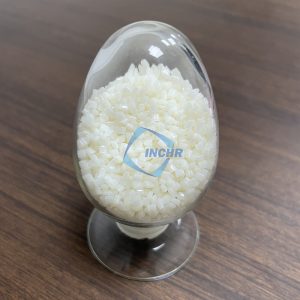
Four Common Risks During Product Development
1. Warpage and Dimensional Variation
Carbon fibers can align with the direction of melt flow during injection molding. This may cause the material to shrink differently in different directions. Thin walls, large flat surfaces, ribs, and uneven wall thickness can make dimensional control more challenging.
To reduce risk, engineers should review gate locations, wall thickness transitions, cooling conditions, and critical assembly dimensions before finalizing the mold.
2. Unexpected Changes in Impact Performance
Higher stiffness does not automatically mean better impact resistance. Adding reinforcement changes the balance between rigidity and deformation, and the result varies by grade and fiber loading.
For clips, snap-fit features, thin connecting sections, or components exposed to repeated impacts, validate the actual design rather than relying on tensile strength alone.
3. Inconsistent Electrical Performance
Carbon fiber reinforced PC may be designed for applications requiring controlled electrical resistance. However, its electrical behavior depends on the formulation and the distribution and connectivity of fibers throughout the compound.
If the application involves ESD protection or electrical discharge control, specify the required resistance range and test method. You can also explore INCHR’s ESD-modified plastic material solutions to identify potentially relevant material options. Confirm the electrical properties of the specific grade before selecting it for a critical application.
4. Processing and Surface Defects
Poor moisture control, unsuitable molding parameters, or an incompatible mold design can contribute to surface defects and inconsistent molded parts. Carbon fiber reinforcement may also affect melt flow and the final surface appearance.
Follow the selected grade’s processing guidance and evaluate samples produced under realistic manufacturing conditions.
A Risk-Based Validation Plan
Instead of testing every property without a clear priority, build a validation plan around the most important failure modes for the application.
| Development stage | Main risk to investigate | Recommended check |
|---|---|---|
| Material screening | Grade does not meet requirements | Review technical data and sample properties |
| Prototype design | Weak areas or excessive deformation | Evaluate load paths, corners, ribs, and connections |
| Mold trial | Warpage or dimensional variation | Measure critical dimensions and inspect flatness |
| Functional testing | Failure under actual use | Test impact, loading, temperature, or repeated operation |
| Production qualification | Batch-to-batch variation | Establish acceptance criteria and incoming quality checks |
The test methods and acceptance limits should reflect the finished product’s requirements. A material suitable for a rigid electronic enclosure may not be appropriate for a flexible snap-fit component, even if both use the same base polymer.
For standardized testing, consult ASTM International and identify methods appropriate to the material property and specimen being evaluated.
How to Define a Useful Material Specification
A purchasing description such as “black carbon fiber PC” is usually not enough to ensure consistent supply. A stronger specification describes the performance the finished part must achieve.
Consider including the following information:
- Mechanical requirements: Required stiffness, strength, impact behavior, and loading conditions.
- Dimensional requirements: Critical tolerances, flatness, shrinkage considerations, and assembly fit.
- Electrical requirements: Target surface or volume resistivity when electrical performance is necessary.
- Processing requirements: Injection molding or extrusion, component geometry, and relevant production constraints.
- Quality requirements: Test methods, inspection criteria, documentation, and batch consistency expectations.
These details help the material supplier recommend a suitable grade and reduce avoidable trial and error during development.
Working With an Engineering Plastics Supplier
A capable supplier should help connect material properties with the needs of the finished product. Ask for grade-specific technical data, recommended processing conditions, sample availability, and support for evaluating application requirements.
INCHR, established in Dongguan, China, in 2012, focuses on ESD plastics and modified polymer materials. Its product portfolio includes carbon fiber reinforced compounds and ESD masterbatches. For projects requiring a particular combination of mechanical and electrical performance, discuss the application requirements with the team and confirm the availability and suitability of the proposed grade.
If you are comparing options for an upcoming project, visit the INCHR engineering plastics product center to review the available material solutions and identify the most relevant product for further technical evaluation.
Conclusion
Successful use of carbon fiber reinforced PC depends on more than choosing a reinforced resin. Engineers should anticipate dimensional variation, verify impact performance, define electrical requirements where necessary, and validate the material in representative molded parts. A clear specification and a structured testing plan can help reduce development delays and improve production consistency.
Frequently Asked Questions
1. What is the biggest design risk with carbon fiber reinforced PC?
One important risk is directional shrinkage and warpage caused by fiber orientation during molding. The degree of risk depends on the grade, component geometry, and processing conditions.
2. Does higher carbon fiber content always improve performance?
No. Increasing fiber content can improve selected properties but may also affect impact behavior, flow, surface appearance, and processing. The optimum formulation depends on the application.
3. How can I check whether carbon fiber reinforced PC meets ESD requirements?
Define the required resistance range and applicable test method, then request grade-specific data and verify performance through testing. Do not assume every carbon fiber reinforced PC grade provides the same electrical behavior.
4. What should be tested before mass production?
Evaluate the properties critical to the application, such as dimensions, mechanical performance, surface quality, and electrical behavior where applicable. Include representative molded parts in validation.
5. What information should I provide when requesting a material recommendation?
Provide the intended application, manufacturing process, operating environment, mechanical requirements, dimensional tolerances, electrical requirements, and expected production volume.