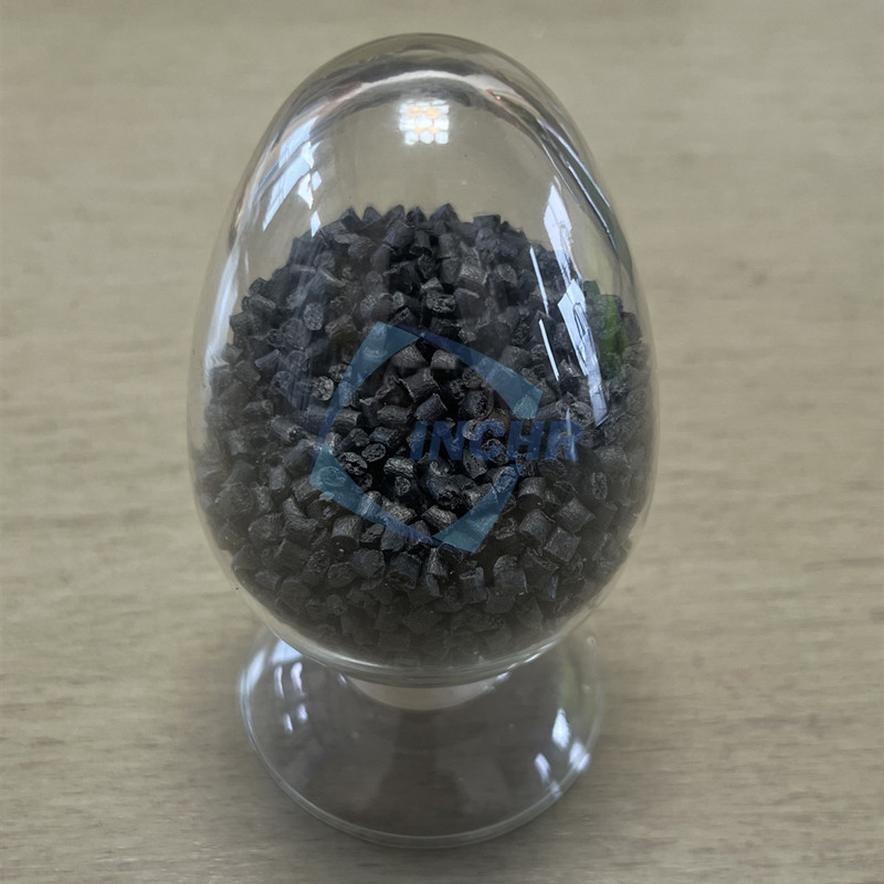
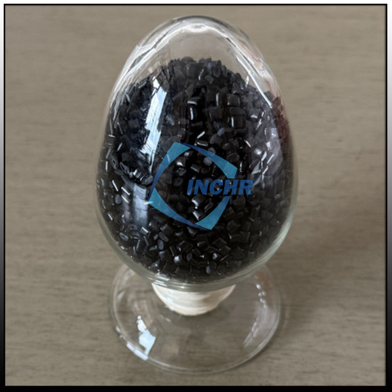
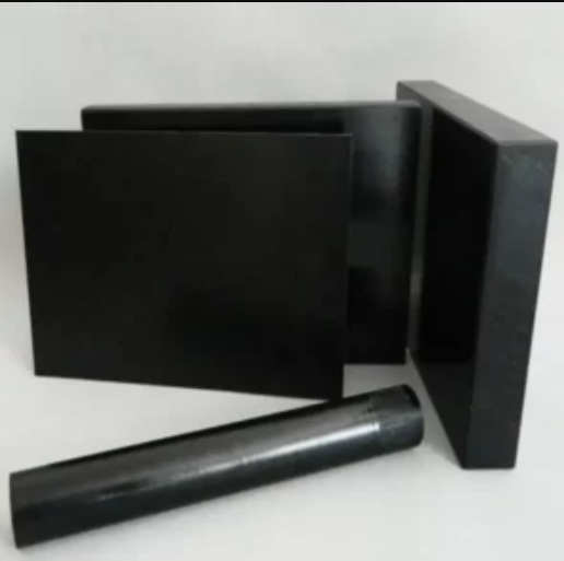
Carbon Fiber Reinforced Polymer (CFRP) are celebrated for revolutionizing aerospace and automotive design with unmatched strength-to-weight ratios. Yet, reducing them to mere “lightweight alternatives” overlooks their true engineering potential. At INCHR-ESD, we see CFRP selection as a systems-level decision – where mechanical properties, environmental resilience, electrical behavior, and manufacturability intersect. Here’s how to navigate beyond marketing hype to optimize performance.

1. The Core Triad: Fiber, Matrix, Interface – Why All Three Dictate Success
Every Carbon Fiber Reinforced Polymer is performance hinges on three interdependent elements:
Carbon Fiber Type/Form:
Standard Modulus (T300): Cost-effective for structural parts (drones, sporting goods).
*Intermediate/High Modulus (T800/M55J)*: Demanding aerospace applications (wing spars, fuselage frames).
Fiber Architecture: Unidirectional tape (max strength directionally) vs. woven fabric (impact resistance) vs. chopped fiber (complex molds).
Polymer Matrix Criticality:
Thermosets (Epoxy, Vinyl Ester): Superior adhesion, high temp tolerance (>120°C), but brittle fracture behavior.
Thermoplastics (PEEK, PAEK, Nylon): Impact toughness, recyclability, faster processing – ideal for medical/automotive.
Fiber-Matrix Interface: The “make-or-break” zone. Surface treatments (sizing) must:
Chemically bond fiber to resin
Survive processing temperatures
Resist operational moisture/chemicals
Failure Insight: Delamination often starts at weak interfaces – not fiber failure.
2. The Overlooked Factor: Environmental Degradation Mechanisms
CFRP don’t fail in labs – they fail in real-world conditions. Key threats:
| Threat | Impact on CRP | Mitigation Strategy |
|---|---|---|
| UV Exposure | Matrix yellowing/embrittlement | UV-stabilized resins (e.g., ASA cap layers) |
| Hydrolysis | Reduced Tg in polyamides (nylons) | Anhydride-cured epoxies; moisture-resistant sizings |
| Galvanic Corrosion | Carbon fibers corrode adjacent metals | Dielectric barrier layers (fiberglass isolation) |
| Creep | Thermoplastics deform under sustained load | Cross-linked thermosets; carbon nanotube reinforcement |
3. Electrical Behavior: From Hazard to Function
While standard CFRPs are conductive longitudinally, their transverse resistivity varies wildly:
Insulative Risk: Epoxy matrix isolates fibers → surface resistivity >10¹² Ω/sq (ESD hazard).
Controlled Conductivity: For EMI shielding or ESD safety (e.g., semiconductor fixtures):
Modified Resins: Intrinsically conductive polymers (PANI, PPy) blended into matrix.
Hybrid Reinforcements: Carbon + nickel-coated carbon fibers for isotropic conductivity.
Surface Engineering: Plasma treatment for uniform resistivity (10⁴–10⁹ Ω/sq).
4. Manufacturing Realities: Cost vs. Complexity
Selecting CFRP isn’t just material science – it’s production economics:
| Process | Best For | CRP Limitations | INCHR-ESD Solution |
|---|---|---|---|
| Autoclave | Aerospace primary structures | High energy cost; size constraints | Out-of-autoclave (OoA) prepregs |
| Compression Molding | Automotive volumes (≥10k parts/yr) | Limited geometric complexity | Tailored charge patterns + multi-axis presses |
| Additive Manufacturing | Prototypes; topology-optimized parts | Anisotropic strength; void content | Continuous fiber 3D printing + in-situ consolidation |
5. Carbon Fiber Reinforced Polymer in Extreme Environments: Case Studies
Application 1: Downhole Oil & Gas Tools (180°C, H₂S exposure)
Standard CFRP Failure: Nylon matrix hydrolyzes; epoxy softens above Tg.
Our Approach:
Matrix: Sulfonated PEEK (chemical resistance)
Interface: Ceramic nano-coatings on fibers
Result: 2x service life vs. stainless steel.
Application 2: Cryogenic UAV Fuel Tanks (-196°C liquid hydrogen)
Standard CFRP Failure: Microcracking from thermal cycling.
Our Approach:
Matrix: Cyanate ester (low CTE)
Architecture: Quasi-isotropic layup + elastomeric interleaves
Result: Zero leakage after 500 thermal cycles.
6. The Sustainability Paradox: Recycling vs. Performance
“Recyclable CFRP” often sacrifices properties. We balance both:
Thermoplastic Pathways:
Mechanical Recycling: Shredded CFRP → injection molding pellets (30% strength retention).
Chemical Recycling: Depolymerize matrix → recover pristine fibers (INCHR-ESD pilot line).
Thermoset Solutions:
Vitrimer matrices: Heat-triggered bond exchange → reprocessable epoxies.
Bio-resins: Soybean/epoxy hybrids with 70% bio-content.
Why INCHR-ESD Delivers Where Generic Carbon Fiber Reinforced Polymer Fail
We engineer systems – not just materials:
Application-Led Formulation: Define operational stresses → optimize fiber/matrix pairing.
Interface Mastery: Proprietary sizing chemistries for harsh environments.
Electrical Engineering: From insulating to conductive (10⁻³–10¹² Ω·cm) on demand.
Closed-Loop Production: Recyclable CRP systems without performance trade-offs.
Ready to Spec Smarter?
→ Consult Engineers:[Link to Booking Calendar] – 30-min technical deep dive.
inchr-esd.com
Precision Engineered Carbon Solutions – Beyond the Datasheet.


